🔩 In Cylinder
In-cylinder pressure transducer analysis — see what's happening inside the combustion chamber. Compression events, valve timing, leakage, and combustion quality in real time. This is where the scope becomes your most powerful diagnostic tool.
Why In-Cylinder Testing?
A compression gauge gives you a number. A pressure transducer gives you the whole story. With in-cylinder testing, you can see every valve event, every compression stroke, every combustion pulse — and spot problems that a gauge will never catch.
See Valve Events
Intake open, exhaust open, overlap — all visible in the waveform. Leaking valves show up immediately.
Cranking vs. Running
Cranking compression tells you mechanical health. Running compression shows dynamic behavior under load — two different tests, both critical.
Prove the Fix
Capture before and after. Show the customer, show the advisor, show yourself. The waveform doesn't lie.
Reference Waveforms
These are the foundational captures every tech should know. Click any image to enlarge.
1. Known Good — In-Cylinder with VVT
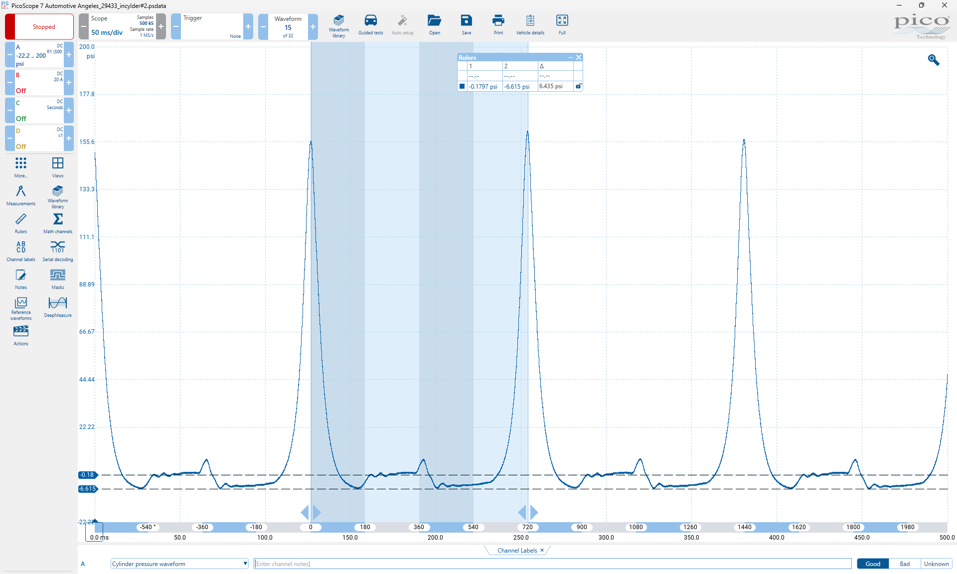
PicoScope capture showing repeating compression peaks at ~155–170 PSI across multiple engine cycles. This is what a healthy cylinder looks like — consistent peak heights, clean valleys returning to baseline near 0 PSI, and symmetrical compression events.
Key takeaway: Uniform peaks = uniform cylinders. Any cylinder significantly lower or shaped differently needs further investigation.
2. Running Compression — Annotated Template
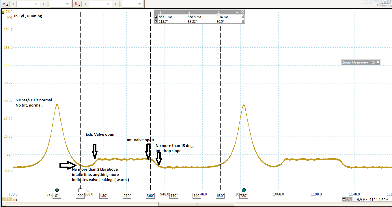
This is the annotated teaching reference for running compression. At roughly 7,194 RPM, the compression peaks hit ~60–65 PSI — which is normal for a running engine. The annotations call out the critical checkpoints:
- 60 lbs ±10 is normal — no tilt, consistent
- Exhaust valve open / Intake valve open events clearly labeled
- No more than 2 lbs above intake line — anything more indicates a leaking valve (warm engine)
- No more than 15° intake drop slope — steeper drop = intake sealing issue
Pro tip: Always run this test on a warm engine. Cold engines will show different numbers and you'll chase false positives.
3. Cranking Compression View
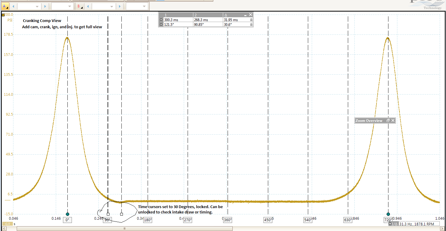
Cranking compression at ~200 RPM showing a healthy peak of ~178 PSI. One full 720° cycle is visible with a single tall, symmetrical compression peak. The time cursors are set at 30° intervals for measuring timing events.
- 178 PSI cranking — strong and healthy
- Symmetrical peak — no flat tops (valve leakage) or irregular shapes
- Cursors at 30° — can be unlocked to check intake draw or timing
- Add CKP, CMP, ignition, injector signals for the complete diagnostic picture
Next step: Overlay a cam and crank signal with this capture to correlate timing events to cylinder pressure. That's where the real diagnostic power is.
What to Look For
⚠ Leaking Exhaust Valve
Pressure above the intake line by more than 2 PSI on a warm engine. The exhaust valve isn't sealing — combustion pressure bleeds past it.
⚠ Leaking Intake Valve
Steep drop slope exceeding 15° on the intake side. The valve isn't closing fast enough or sealing properly.
⚠ Leaning Tower of Pisa
If the compression peak is leaning, it always means a piston or ring issue. The lean means less air on the way down than on the way up. Science.
✓ Healthy Cylinder
Symmetrical peaks, consistent height across all cylinders, clean return to baseline. No tilting, no flat tops, no irregularities.
Additional Captures & Discussion
This section will grow as more captures, stories, and analysis are added. Have an in-cylinder capture to share? Send it in with the vehicle info and what you found.
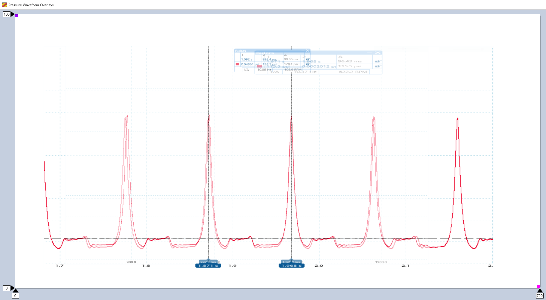
⚠ Cylinder Offset — Two Cylinders Overlaid
From the Field
Two in-cylinder pressure traces overlaid for comparison. You can clearly see the offset between the two cylinders — one is producing consistently lower peak pressure than the other, with a slight timing shift between them.
The waveform shapes are clean and repeatable — no misfires, no catastrophic failures. But that peak pressure difference tells you something's off. One cylinder isn't sealing as well as the other.
The fix: Resolved with services. The scope caught a problem still in the “fixable with maintenance” window — before it became a teardown.
The lesson: Overlaying two cylinders is one of the fastest ways to find a weak one. Even when both look “normal” alone, the offset jumps out when you stack them.
More captures and stories coming. Have one to share?
Submit a Capture →